(To play the video, please click on the image above)
Image: Topography and bathymetry at the triple junction of the Afar triangle (ETOPO1, 2008).
(To play the video, please click on the image above)
Image: Topography and bathymetry at the triple junction of the Afar triangle (ETOPO1, 2008).
Triple junctions are the places on Earth where three lithospheric plates border each other. The irregular plate pattern requires a whole series of such junctions with three adjacent plates.
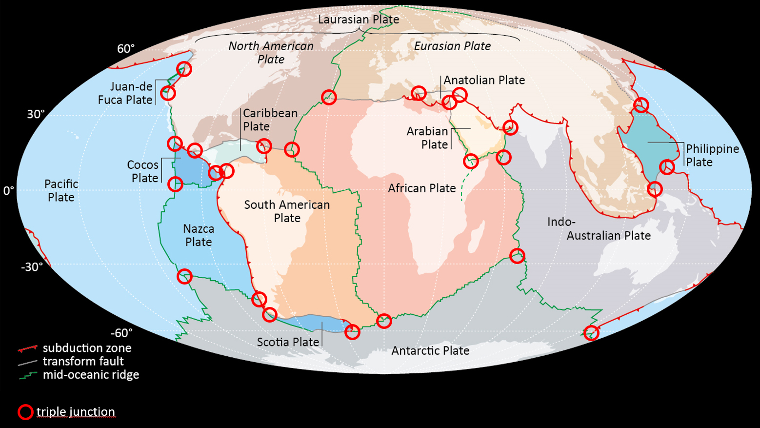
Fig.4.4.1: Earth’s plate pattern. Highlighted with red circles are triple junctions (modified after Meschede & Warr, 2019).
Figure 4.4.1 shows the Earth’s plate pattern with some triple junctions. If we also count all the small plates, we can assume there are around 50 independent plates today. An inevitable geometric consequence of this large number of plates is that there are lot of triple junctions where three plate boundaries meet. All plate boundaries are dynamic boundaries that are subject to constant change: at divergent plate boundaries the plates move away from each other, at convergent plate boundaries they move towards each other and at transform faults they slide past each other. There are no junctions with four meeting plate boundaries because due to the dynamic development they would be converted back into triple junctions immediately after their formation.
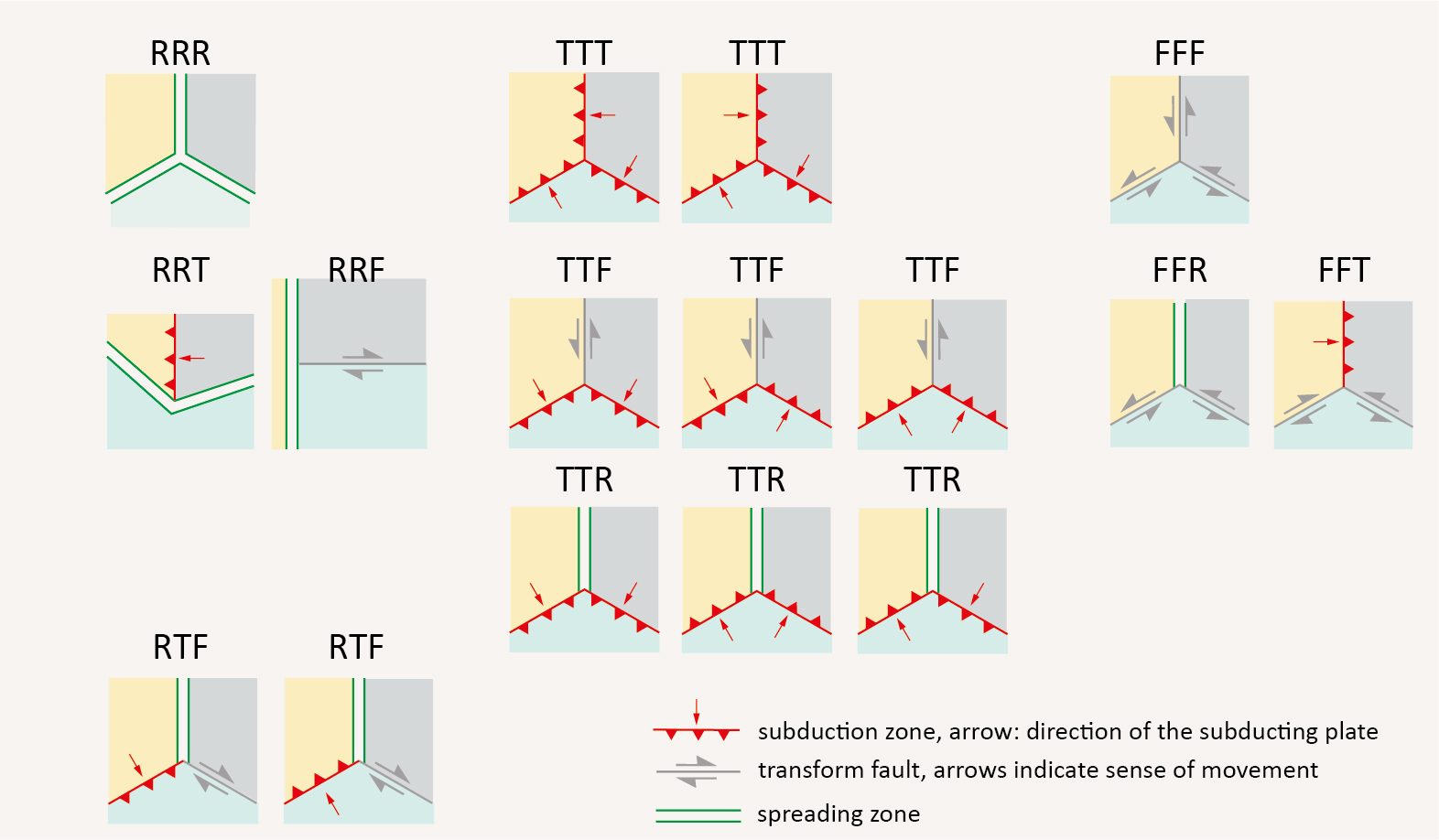
Fig.4.4.2: Different constellations of triple junctions. R – mid-oceanic ridge; T – deep-sea trench, subduction zone; F – transform fault. Meschede (unpubl. 2024).
Various options for triple junctions are shown in Fig. 4.4.2. There are triple junctions in different constellations, all based on the three possible types of plate boundaries, ridge = R, deep sea trench – T, transform fault = F. Not all constellations shown in the figure are stable, some are not at all possible. The subduction polarity, i.e. which plate is subducting and which is the overriding plate, also plays a role in the development of triple junctions.
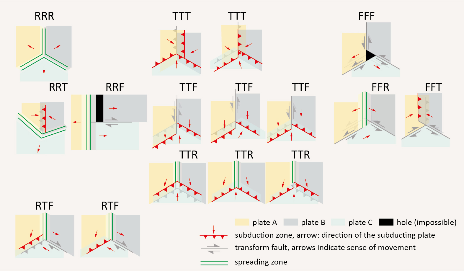
Fig.4.4.3: Plate movements at triple junctions. R –mid-oceanic ridge; T – deep-sea trench, subduction zone; F – transform fault. Black = formation of a hole – impossible constellation. Meschede (unpubl. 2024).
Figure 4.4.3 shows the same constellation of triple junctions as the previous figure, except that here the plates, which are shown in different colors (yellow, gray, light blue), have been moved slightly away from their original position. The direction of movement of the plates is marked by the red arrows. At some triple junctions you can see that holes would appear – here in black – if you move the plates in the direction of the arrows. Of course, holes in the crust cannot arise, i.e. such triple junction constellations are not possible. If, for example, three transform faults were to actually come together, as in the upper right example, such a triple junction would immediately be transformed in such a way that a stable situation would arise.
In the middle in the third row, three different possibilities for a TTR triple junction, two subduction zones and a mid-ocean ridge, are shown. If the direction of subduction is the same as in the left two TTR triple junctions, the triple junction remains. However, if the subduction direction is in the opposite direction, a new transform fault will arise between the two subduction zones. A downward extension of the mid-ocean ridge would also be possible here.
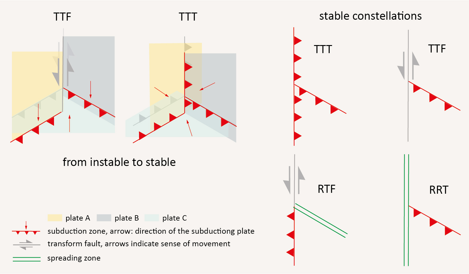
Fig.4.4.4: Examples of stable triple junctions. R –mid-ocean ridge; T – deep-sea trench, subduction zone; F – transform fault. Black = formation of a hole – impossible constellation. Meschede (unpublished 2024).
In Fig. 4.4.4 two triple junctions are slightly enlarged. The example on the left shows a TTF triple point. Where one subduction zone was previously at an angle to the other, a transform fault has formed that runs parallel to the existing one. The left subduction zone, however, no longer ends at a triple junction. At the TTT triple point with three subduction zones it is similar; due to the plate movement, the boundaries shift so that in the end at the triple junction two subduction zones run parallel and only one at an angle to it. Here the subduction zone was extended and the lower left subduction zone no longer ends at a triple junction.
On the right side of the figure, various constellations are shown that can be viewed as stable at least over certain geological periods of time. In all cases, two plate boundaries run parallel to each other at the triple junction.
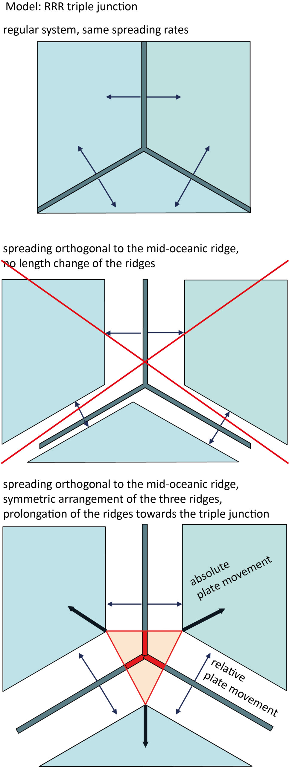
Fig.4.4.5: The principle of movement at an RRR triple junction. R – mid-ocean ridge. Above: Initial situation of the model with symmetrical arrangement of the ridges, equal spreading rates, symmetrical spreading. Middle: Symmetrical spreading perpendicular to the ridge alone does not produce a consistent result. Below: Symmetrical spreading on all ridges at the same time leads to the displacement of the three ridges away from the triple junction – red lines. In the reddish area, oceanic crust is newly formed in addition to the spreading zone. Meschede (unpubl. 2024).
The actual movement at a triple junction is explained using the simplest model, the RRR triple junction, where three mid-oceanic ridges meet. In this example, a very simple model is used with a star-shaped arrangement of the three ridges, each at 120° to each other. It is further assumed that the spreading speed is the same on all ridges (Fig. 4.4.5, top). There exist several examples of this on Earth, two of which are shown in the next video.
In general, spreading at mid-oceanic ridges is always symmetrical and occurs perpendicular to the ridge axis, i.e. the plates move orthogonally away from the ridge. There is no mechanism that could explain why more oceanic crust is formed on one side of the spreading zone than on the other. Therefore, symmetrical spreading is always assumed.
If you try to carry out the spreading purely geometrically orthogonal and symmetrically to the spreading ridge, you will encounter difficulties, as the three ridges practically hinder each other (Fig. 4.4.5, middle). However, if, in addition to the newly formed oceanic crust on both sides of the ridges, new oceanic crust is also formed in an area around the triple junction. With this, the symmetrical development can be achieved without any problems (Fig. 4.4.5, below).
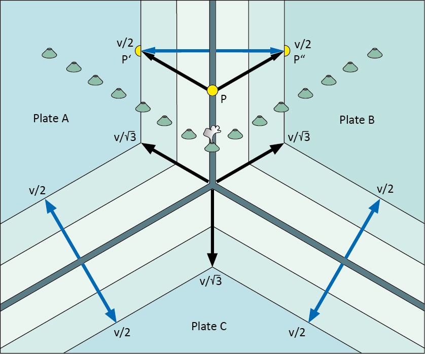
Fig.4.4.6: Directions and plate movement velocities of three plates at an RRR triple point. The relative movements of two plates to each other do not correspond to the absolute plate movement, which is traced, for example, by volcanic chains that were formed at a (stationary) hotspot. From Frisch & Meschede (2021).
In Fig. 4.4.6, an RRR triple point is shown again, here in combination with a hotspot volcano under the ridge axis, whereby the volcano or the volcanic chain formed on the mid-oceanic ridge traces the absolute plate movement. This and the relationship between hotspot track and relative to absolute plate movement will be discussed in the next video.
Geometrie von Tripelpunkten


![]()
©2022 Deutsche Geologische Gesellschaft - Geologische Vereinigung